STM32 bare-metal made easy
Some time ago, I wrote a post explaining why a minimal knowledge of bare-metal programming is a must for a modern MCU programmer.
Here is a follow up, showing a minimal example with a cheap, though quite popular hardware setup. The application will show you how to:
prepare the Makefile and linker script with no external dependencies;
write the minimal code to boot the board, set the clock and initialize the UART;
have a loop writing data to UART, once every second.
Hardware setup
To compile, flash and run the example, you need:
an ARM gcc toolchain running on a Unix system; for instance, I am using a Ubuntu Linux OS, with arm-none-eabi-gcc, version 4.9.3, installed from default repository;
a proper tool for flashing the board; the provided Makefile relies on the opensource stlink tool; you can change to your favourite one, just adapting the Makefile
flashtarget;a USB-to-TTL converter, to show UART output on your preferred serial port client (e.g. putty, minicom or similar);
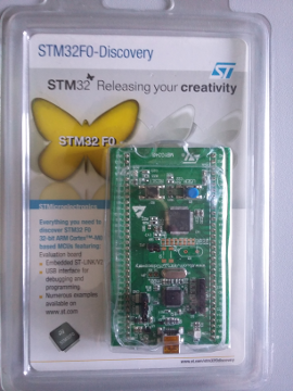
a STM32F0-Discovery board (see image below); it will be refferred to as the "target board" from now on.
What you only need is:
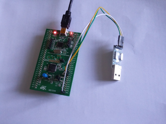
connect the mini-USB on the target board to an USB port of your PC: this both powers the board and is used to flash it;
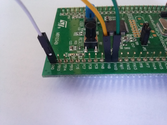
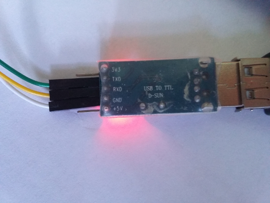
connect the USB-to-TTL to the target board, as shown in the images: PA10 is the UART RX pin of the board, and must be connected to TXD on the USB-to-TTL adapter (green wire), whereas PA9 must be connected to the RXD on the adapter (yellow wire); white wire is the ground:
How to download, compile and flash the firmware
First of all, you can clone my github repository:
$  git clone git@github.com:colosimo/stm32f0-baremetal.git
Cloning into 'stm32f0-baremetal'...
remote: Counting objects: 24, done.
remote: Compressing objects: 100% (19/19), done.
remote: Total 24 (delta 3), reused 21 (delta 3), pack-reused 0
Receiving objects: 100% (24/24), 8.99 KiB | 0 bytes/s, done.
Resolving deltas: 100% (3/3), done.
Checking connectivity... done.
Then, run make inside it:
    $ cd stm32f0-baremetal/
    $ make
    arm-none-eabi-gcc -c -mthumb -Wall -Werror -Os -mcpu=cortex-m0 -ggdb -nodefaultlibs -nostdlib -nostartfiles -ffreestanding -Iinclude -o init.o init.c
    arm-none-eabi-gcc -c -mthumb -Wall -Werror -Os -mcpu=cortex-m0 -ggdb -nodefaultlibs -nostdlib -nostartfiles -ffreestanding -Iinclude -o kprint.o kprint.c
    arm-none-eabi-gcc -c -mthumb -Wall -Werror -Os -mcpu=cortex-m0 -ggdb -nodefaultlibs -nostdlib -nostartfiles -ffreestanding -Iinclude -o main.o main.c
    arm-none-eabi-ld init.o kprint.o main.o -Tstm32f4xx.ld -o stm32f0-demo.elf
    arm-none-eabi-objcopy -O binary stm32f0-demo.elf stm32f0-demo.bin
    $ ls -lrt stm32f0-demo.bin
-rwxrwxr-x 1 colosimo colosimo 1056 apr 11 11:23 stm32f0-demo.bin
If everything goes as expected, you will now have the stm32f0-demo.bin binary
file, ready to be flashed. Note it's extremely tiny in terms of flash occupancy,
mine is only 1056 bytes.
A facility for binary flashing is provided by the make flash target.
If your stlink tools are properly installed, and the target board is connected,
you should see something like this:
$ make flash
st-flash write stm32f0-demo.bin 0x8000000
st-flash 1.3.1-19-g55c0572
2018-04-11T15:11:05 INFO src/common.c: Loading device parameters....
2018-04-11T15:11:05 INFO src/common.c: Device connected is: F0 device, id 0x20006440
2018-04-11T15:11:05 INFO src/common.c: SRAM size: 0x2000 bytes (8 KiB), Flash: 0x10000 bytes (64 KiB) in pages of 1024 bytes
2018-04-11T15:11:05 INFO src/common.c: Attempting to write 1056 (0x420) bytes to stm32 address: 134217728 (0x8000000)
Flash page at addr: 0x08000400 erased
2018-04-11T15:11:05 INFO src/common.c: Finished erasing 2 pages of 1024 (0x400) bytes
2018-04-11T15:11:05 INFO src/common.c: Starting Flash write for VL/F0/F3/F1_XL core id
2018-04-11T15:11:05 INFO src/flash_loader.c: Successfully loaded flash loader in sram
1/1 pages written
2018-04-11T15:11:05 INFO src/common.c: Starting verification of write complete
2018-04-11T15:11:05 INFO src/common.c: Flash written and verified! jolly good!
Now, open your minicom or equivalent tool on the USB port given by the USB-to-TTL device, and, after a reset (black button on the target board), you should see a dot (.) written once every second, and a newline once a minute:
Hello from ff_demo
............................................................
............................................................
......
Source code explanation
Some more details about how the code works. I suggest to download the STM32Fxx user manual, available on ST site:
https://www.st.com/resource/en/reference_manual/dm00031936.pdf
1. The Makefile
The Makefile does not contain anything exciting; it's the mostly simplified version of a common cross-compile Makefile; worth to note here, are a couple of details:
The "magic" rule to convert any .c to its corresponding .o:
%.o: %.c
        $(CC) -c $(CFLAGS) $(INCFLAGS) -o $@ $<
The CFLAGS settings, used to tell what's the target cpu (Cortex M0) and meant to have no dependencies, even excluding the stdlib:
CFLAGS += -mthumb -Wall -Werror -Os -mcpu=cortex-m0 -ggdb -nodefaultlibs \
        -nostdlib -nostartfiles -ffreestanding
2. The linker script
This is quite an ugly beast for most people (including myself!); the reason is that, when compiling for a PC running an operating system, you won't most ever need know about its existence, but implicitely rely on the one provided by your compiler. The linker script becomes a useful tool when you have all of your RAM and flash under your control, like it happens in bare-metal programming. The linker script is then used to tell your toolchain how to compose your compiled object (.o files) in order to obtain the final binary. The script is heavily based on sections, or segments (for a quick introduction, Wikipedia Data Segment webpage is a good choice).
Linker script syntax is not straightforward, so I won't spend too much time on it, just I will point out what's happening on the first lines, inside the .text section.
.text 0x08000000: {
        *(isrv_sys); /* Interrupt Service Routine Vector - System */
        *(isrv_irq); /* Interrupt Service Routine Vector - Peripherals IRQs */
        . = 0x000000C0;
        *(.text)
}
Basically, the above snippet says this:
the text code will be placed at address 0x08000000; this is the internal flash base address in STM32F0xx chips;
the first bytes in the flash will contain the Interrupt Service Routine vector (system and IRQ);
the proper code will be placed at 0xC0 (192) delta: 192 bytes is the size of the ISR vector(s), so the code is put right after them.
This is the basic setup of any Cortex-M system: you have to prepare your flash with the ISR vectors, then, at boot, the second (32 bits) element of the vector is used as the address of the reset routine, which is the entry point for the execution. A good introduction to how ARM systems boot are the ARM documentation pages themselves.
3. The include/ directory
Here is where I put some generic defines, used inside the .c, and I often copy
them from one project to another, as they provide some basic macros and defines;
they should be commented enough, so no need to tell more. The most relevant file
here is the basic.h file, where macros for registers manipulations
(e.g. wr32, rd32, etc) are defined.
Other relevant files are:
cpu.h: hosts the definitions for some common registers in ARM architecture;stm32f411x.h: defines registers for the ST SoC;gpio.h: defines some helpers for GPIOs handling.
3. The init.c file
It contains the code automatically called by the chip at startup. As explained above, the cpu expects a list of function pointers to be called in case of interrupts or special events; one of this is the reset; so this is how the isrv_sys array looks like:
static const void *attr_sect("isrv_sys") _isrv_sys[] = {
        /* Cortex-M0 system interrupts */
        STACK_TOP,      /* Stack top */
        isr_reset,      /* Reset */
        isr_nmi,        /* NMI */
        isr_hf, /* Hard Fault */
        0,                      /* Reserved */
        0,                      /* Reserved */
        0,
        [...]
The first element is the RAM stack top address; the second one is the reset
routine, here called isr_reset (but you can choose your preferred name),
and defined in the same file.
Regarding the isr_reset routine, these are the steps it performs:
load the
datasection to RAM:datasection is the one containing any preinitialized value in the code;set
bsssection to zero: bss is the static RAM used by the code; it differs withdatasection in having implicit zero value at boot;configure clock and system ticks; system ticks is a variable setted to increment once every 1ms, and can be used for time keeping (see
isr_systickfunction);initialize the UART.
4. The main.c file
What I here propose is a very simple main, working as a basic clock on UARt: an infinite loop, waiting for system ticks increments, and writing a dot once every second (1000 system ticks), and a newline once a minute.
5. Conclusions
You can use the code here commented as an exercise to understand how an ARM-based MCU work, with no helps from SDKs nor Operating Systems. With some efforts, the same code can be expanded in order to support medium-complexity applications, with essential-only stuff, direct access to registers small flash, occupancy and full control of what's being done by your code.